Plate Heat Exchanger As Vaporizer and Condenser-2
Plate heat exchangers (PHEs) have been installed in larger heat pump systems and refrigeration systems since the 1980s. Tech-nicians who deal with these systems need to know some specific details of how they work.
Part one of this article covered PHE design, on-site assembly and service, leak indication, freezing risk, and resistance from vibration, pressure, and seismic occurrences. This week the article continues its discussions of the plate heat exchanger as vaporizer and condenser.
OIL
In ammonia systems, small quantities of oil can accumulate at the inlet. Oil draining at the lowest point can be used, but is not mandatory. The oil will be entrained in the ammonia and emerge with the partially vaporized fluid, thanks to the high shear forces and the turbulent flow even at low velocities.
The oil content in CFC vaporizers, however, affects heat transfer. At normal oil concentrations of about 1% to 2%, maximum heat transfer is obtained at an exit vapor fraction of about 0.7. Small oil concentrations can have a positive effect on heat transfer; surface tension effects can explain this.
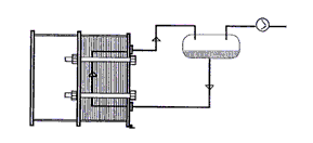
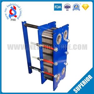
Plate Heat Exchanger as submerged vaporizer with thermosiphon circulation.
DX VAPORIZATION
Plate heat exchangers have so far been used at capacities up to about 500 kW using direct expansion (DX). It is primarily the brazed PHEs used at these small capacities.
Pure counter-current operation provides reliable superheating. The pressure drop can be kept low in order to minimize the temperature drop for the refrigerant, and to keep the specific volume at the outlet as low as possible.
Distribution of the CFCH medium (usually as a two-phase mixture from the expansion valve) to the PHE channels is good provided the number of channels is not excessive. With direct expansion, this is more important, since channel distribution is a function of the relation between channel and inlet-outlet pressure drops.
An extra restriction at the inlet permits the use of more channels while maintaining good distribution. A fixed throttling at the inlet can, however, lead to difficulties with control; the vaporizing temperature cannot then rise maximally on turndown. The electronically regulated expansion valve cannot easily set the temperature at the vaporizer inlet if a fixed restriction is used.
Oil in the channels is entrained and removed from the vaporizer. At small fixed turndown, small quantities of CFC(H)/oil may remain in the inlet manifold, which has a small volume.
Capacity regulation down to about 20% turndown can generally be permitted. The advantage is that the entire heat transfer surface is available for heat transfer at turndown. The vaporization temperature can then lie above design point.
As already noted, low loads can be obtained at small nominal velocities, but the shear forces and turbulence mean that oil will still be swept up and out of the vaporizer.
Choices of vaporizer type and design calculations are made in close cooperation with the designer of the refrigeration plant.

